Top 3 Injection Molding Pitfalls
Before we jump into the injection molding pitfalls you should avoid, here’s a quick review of the Injection Molding Process, Injection Molding Basics, and Rapid Injection Molding.
What is Injection Molding
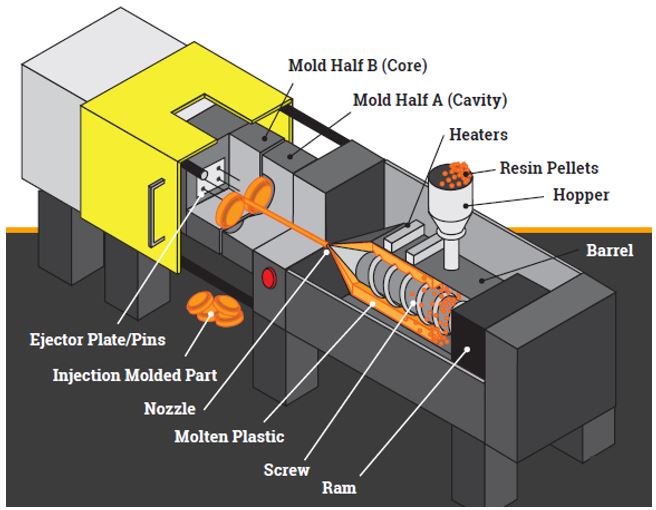
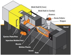
Plastic resin pellets are loaded into the hopper, where it travels into the barrel of the injection molding machine. Through both heat and pressure, the plastic pellets are melted into a molten material that is ready to be injected. As the screw turns it creates pressure which will help push the molten plastic through the nozzle and into the mold.

Our proprietary process engine creates ideal pressure, temperature and time cycle which is critical to creating high quality custom parts. Once the right environment inside the barrel is met, the ram moves forward driving the screw and channeling the molten plastic into the mold cavity through the nozzle. Once allowed to cool, the mold will open and the ejection plate engages, releasing the final part from the mold.
Injection Molding Basics
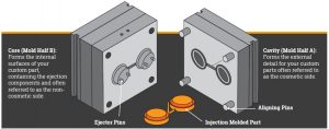
Injection Molds consist of two main components: the mold cavity and the mold core:
CORE (Mold Half B) – forms the main internal surfaces of your custom part
CAVITY (Mold Half A) – forms the major external features
The cavity and core separate (Draw) along the parting line and, with the aid of ejector pins, releases the finished plastic part where the process can be repeated. Depending on your part design, the parting line can either fall on the top, bottom, stepped or angled to accommodate all irregular part features.

High quality, efficient tooling relies heavily on good part design as well as advanced skills in mold design and the manufacturing of the tool. An injection mold is a highly precision tool that must be rugged enough to withstand hundreds of thousands of high-pressure molding cycles. By optimizing your part design and focusing on consolidating many key features, you can reduce your overall investment costs significantly.
Rapid Injection Molding
Rapid injection molding is possible when a manufacturer has developed sophisticated digital manufacturing practices to significantly increase the speed of the mold building process. We can reduce a typical mold build time of 6-18 weeks to just a few days. With this advancement, you can get real injection molded parts to use either as production or prototype.
Producing prototype parts quickly will help you to get your products to market faster than your competition. The cost is often less than what most injection molding companies charge for a prototype mold without the life expectancy limitations. Done correctly, you can often skip rapid prototyping because the process is so fast and affordable allowing you to produce low-volume production quality parts.
By using engineering grade resins, your injection molded prototype parts can be tested under the same conditions as your final parts and can be made of similar, if not the exact, finish materials. This allows you to test in real mechanical, chemical and environmental circumstances and help you create the best possible part design for your product.
With high speed mold making, you can also obtain Bridge Tooling when you need prototypes using real materials or when your project is not quite ready for full production. Essentially bridging the gap between Prototype and high-volume production. Knowing that your Bridge Tool can be used for production parts, backed by a Lifetime Mold Guarantee can help save you time and money and will give you the advantage over your competition.
Click here for more About Injection Molding, and read on to learn about the key pitfalls you should avoid within the injection molding process.
Now, let’s discuss three common injection molding pitfalls: knit lines, sink and warp, and material shrinkage.
Pitfall #1 – Knit Lines
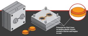
The injection molding process is fairly simple, plastic resin is heated to its melting point and forced through the machine and into your mold to produce your plastic parts. The leading edge of the molten material is often the coolest point and the closest to solidifying. When the molten plastic meets an obstruction, it must travel around and meet at the other side. If the plastic has cooled too much during the injection process it can lead to knit lines in plastic parts when they meet past an obstruction.

ABS is the most common resin to be prone to knit lines. If you are concerned about potential knit lines, turn to the mold flow analysis of your part and address any design issues that can be easily modified. Review similar materials that may be less prone to show knit lines. With good part design and a well-designed mold, knit lines can often be significantly reduced or removed completely. Click here to learn more About Mold Flow Analysis
Pitfall #2 – Sink and Warp
Variations of shrinkage in materials can lead to warp, distortion and dimensional issues with injection molded parts. As the plastic material cools, the molecules that make it up move closer together. If the cooling rate is different, such as thinner or thicker walls the stress caused by cooling can lead to the material wanting to warp. As the plastic in the mold cools from the outside in, it can cause pulling on the outer walls resulting in sink marks. Thinner wall thickness will help to prevent this. Where possible, always try to design a part with thinner and consistent wall sections to minimize warp and sink marks.

Careful consideration to part and mold design must be addressed to create high quality, consistent plastic parts and at Xcentric, we provide you with the tools and experience to reduce or eliminate potential cosmetic or structural defects of your plastic custom parts.
Download: Material Shrinkage Guide
Pitfall #3 – Shrink
With most injection-molded resins, a certain degree of shrink can be expected due to the materials chosen. Some materials tend to shrink more than others so careful consideration on material choice should be made. Rapid changes to wall thickness are the most common cause of shrinkage due to the pressures exerted for the plastic material to fill your mold. When designing your parts try to eliminate thin wall sections leading into thicker wall sections and create parts with uniform wall thickness throughout.
If thick and thin sections are necessary try to transition the change gradually, utilizing angles to help aid the flow of materials throughout your plastic parts. Controlling part shrinkage is critically important especially in tight tolerance plastic parts.
Conclusion
Adhering to best practices can help to avoid injection molding pitfalls. Consider the following “checklist” as a baseline to meeting your part expectations.
Wall Thickness
• Maintain uniform Wall Thickness throughout
• Utilize Ribs to reinforce walls without adding to thickness
• A 10% increase in thickness = 33% increase in stiffness
• Core out unneeded thickness and wall stock
Draft
• Maintain a minimum of 0.5° draft angle on all features perpendicular to the parting line. 1° – 2° is ideal.
Tight Tolerances
• Utilize low-shrinkage materials for parts with tight tolerances
Ribs & Bosses
• Design ribs and bosses to approximately 60% of the joining wall thickness for minimum risk for sink marks.
Undercuts
• Undercuts will add cost to the mold. Minimize them when you can. Otherwise, there are no limits.
Corners and Transitions
• Use gradual transitions if wall thickness must change.
• Corners: R1 + T = R2
DOWNLOAD: Designing for Manufacturability Guide
Interested in obtaining more advice? Reach a Technical Engineer at sales@xcentricmold.com, or call (586) 589-4636