If you design parts for plastic injection molding, you are already familiar with 3D CAD software used in the design process. Depending upon the CAD program and supporting software, very precise, complex parts or products can be designed from them.
Each CAD vendor has its own software with its respective native file formats. And at some point, you may need to share your 3D/2D CAD designs with a customer, partner or rapid manufacturing company.
In this case, both your software and the recipient’s software should have a compatible file format for it to be properly exchanged between one another.
Submitting a 3D CAD file initiates the process for requesting a custom injection molding quote at Xcentric. It includes the submission of a 3D CAD design file for review and enables us to provide feedback and a design for manufacturability review within 24 hours.
In this post you will learn the top design programs used in 3D CAD development and common file formats for sharing 3D CAD and 2D CAD designs.
3D CAD Design Programs
Commonly used design programs in 3D CAD model development include:
- SolidWorks
- CATIA
- UniGraphics/NX
- Autodesk
Each of the programs above vary in features and capabilities.
File Formats for sharing 3D/2D CAD Designs
CAD file formats generally fall into two categories either Native or Neutral (Standard) File formats. Native file formats are proprietary to a particular CAD software maker that are to be used with their own software.
Neutral or Standards were specifically created to encourage interoperability which helps exchange files between different software programs.
Neutral or Standard file formats make it easier to exchange files with someone who uses different CAD software. The most successful native formats are supported by a variety of software. Neutral file formats that can be imported and exported from most design programs include:
- ACIS (.sat)
- IGES (.igs)
- Parasolid (.x_t and .x_b)
- STEP (.stp)
- Stereolithography (.stl). This file format is typically a standard for 3D printing.
ACIS provides 3D modeling functionality which is used by many software developers in industries such as computer-aided design (CAD), computer-aided manufacturing (CAM), computer-aided engineering (CAE), architecture, engineering and construction (AEC).
.IGES/.IGS is a vendor-neutral (not owned by any one company) file format that allows the digital exchange of information from CAD software. “IGES” models with the .igs extension can be used to display various forms of technical information including wiring diagrams, wireframes, and 3D solid models.
Parasolid (.x_t or .x_b) capabilities include model creation and editing utilities such as Boolean modeling operators, feature modeling support, advanced surfacing, thickening and hollowing, blending and filleting and sheet modeling. Most Parasolid files can communicate and migrate only 3D solids and/or surface data. Parasolid files currently cannot communicate and migrate 2D data such as lines and arcs.
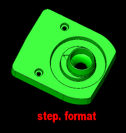
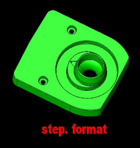
.STP refers to a STEP file, which is an abbreviation for the Standard for the Exchange of Product model data. These files represent 3D objects in CAD software and can contain related information. It was designed as a successor to IGES (.igs), although it has not fully replaced it. STEP files are as close to the universal standard of 3D modeling as is currently available. STEP files are used in many industries and can contain data from the entire life-cycle of a product’s design.
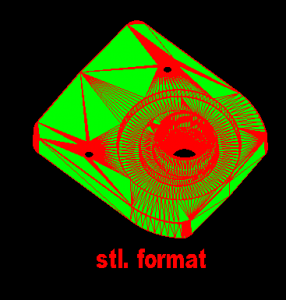
.STL (Stereolithography files) are the default file format for 3D printing. They consist of thousands of triangular polylines that are identified by 3D printing software slicers. As the software “slices” each level of the part it then reads the triangular points and creates “Gcode” locations telling the printer where to move to construct each slice of the part layer by layer. These files are only useful in 3D printing as they are a simplified version of the original part file created to be read by the printer software. They do not contain surfaces or solids needed for manufacturing which is why we request STEP or IGES files. See the example below and the enhanced detail of the original model in comparison to the STL format.


At Xcentric, STEP and IGES files are the preferred neutral file formats for plastic injection molding and STL files for 3D printing only.
We provide a design for manufacturability analysis within 24 hours. If you have a question regarding a specific file format, ask one of our Technical Specialists today at 586-598-4636 or sales@xcentricmold.com.